
1. Start here
What you are building
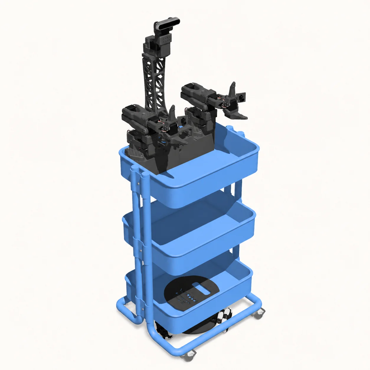
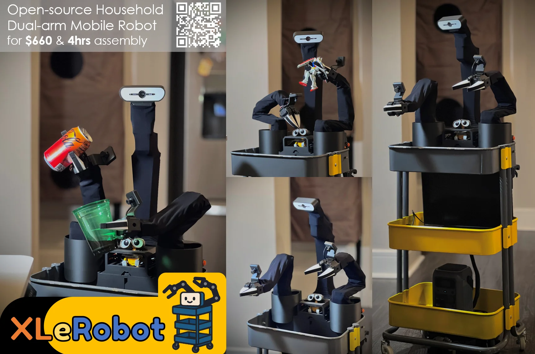
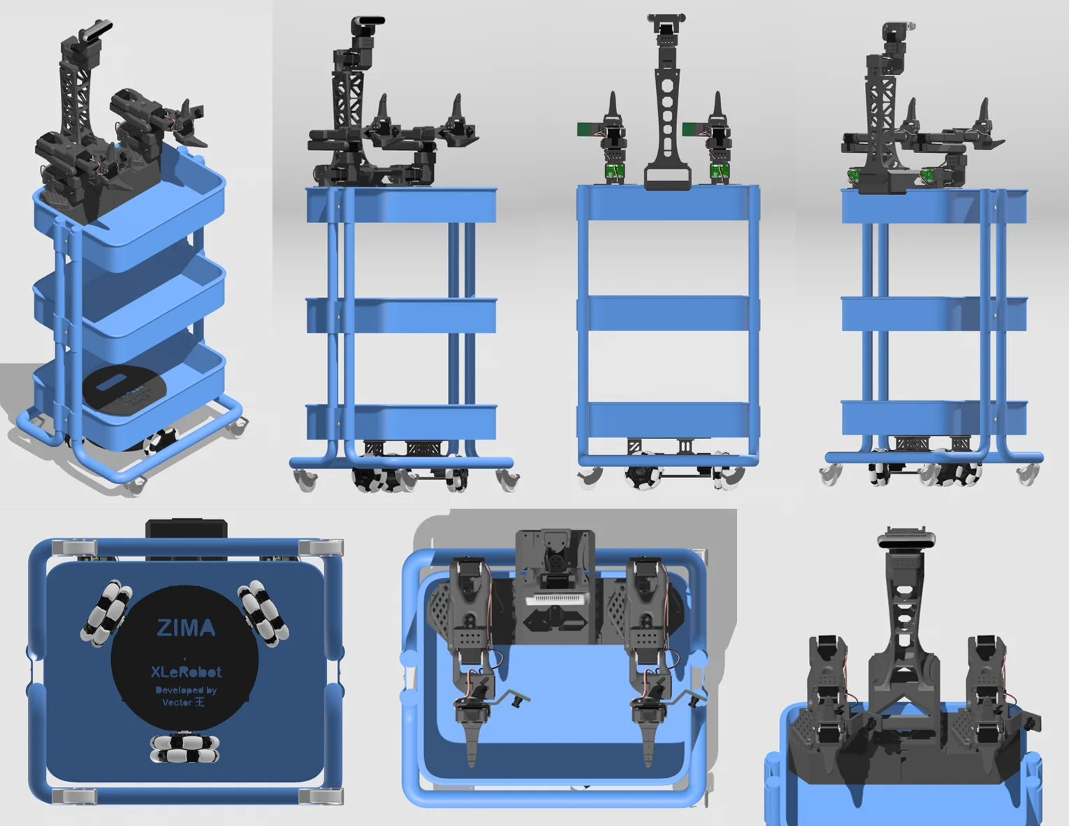
XLeRobot is a dual-SO-101 mobile manipulator. Its hardware combines a RÅSKOG cart, a selectable mobile wheel base, two robot arms, an arm platform, head and camera components, 12V power, and control electronics. Build the independent parts first, then integrate them into the cart.
Mobile base
Choose either the dual-wheel platform or the mecanum-wheel platform before printing its parts.
Two arms
The project uses two SO-101 arms, including their motors, controllers, wiring, and calibration.
Cart platform
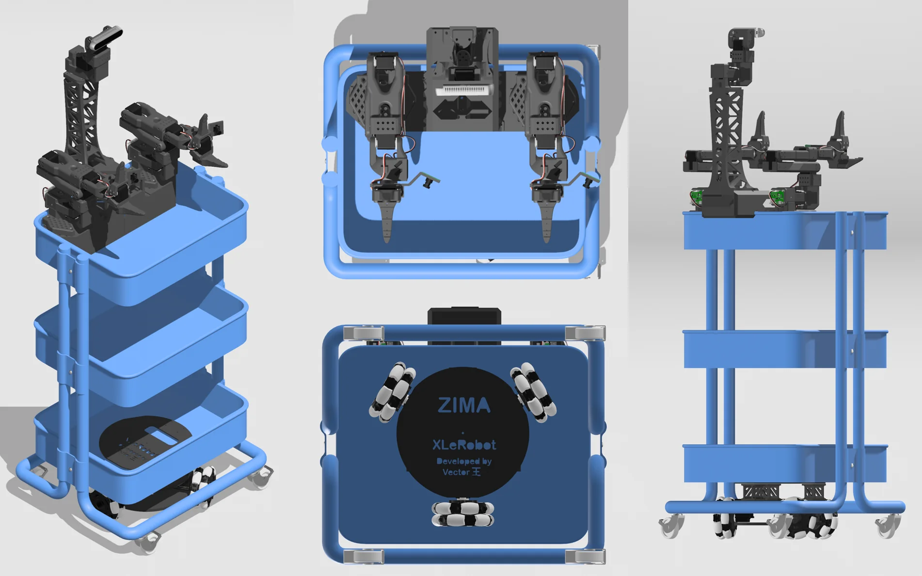
The cart carries the base, arm platform, head, cameras, controllers, cables, and power station.
2. Procurement
Parts and tools
Source the complete hardware set before assembling. The original cost target excludes printing, tools, shipping, and taxes. A basic configuration starts around USD 660 when sourced independently; optional stereo cameras, Raspberry Pi, and RGB-D sensing increase that total.
| Part | Qty. | Purpose |
|---|---|---|
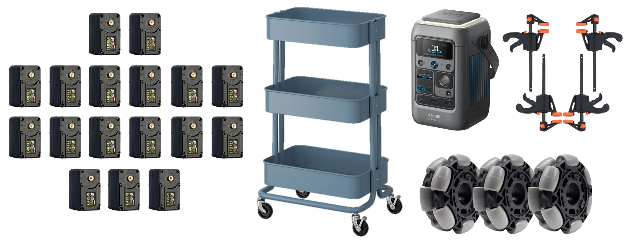
| STS3215 12V servos | 17 | 12 for the arms, 3 for the base, 2 for the head |
| IKEA RÅSKOG utility cart | 1 | Main chassis |
| 12V power station | 1 | Must power two 60 W+ USB-C outputs; add Pi capacity if used |
| 4-inch omni wheels | 3 | Mecanum / omnidirectional configuration |
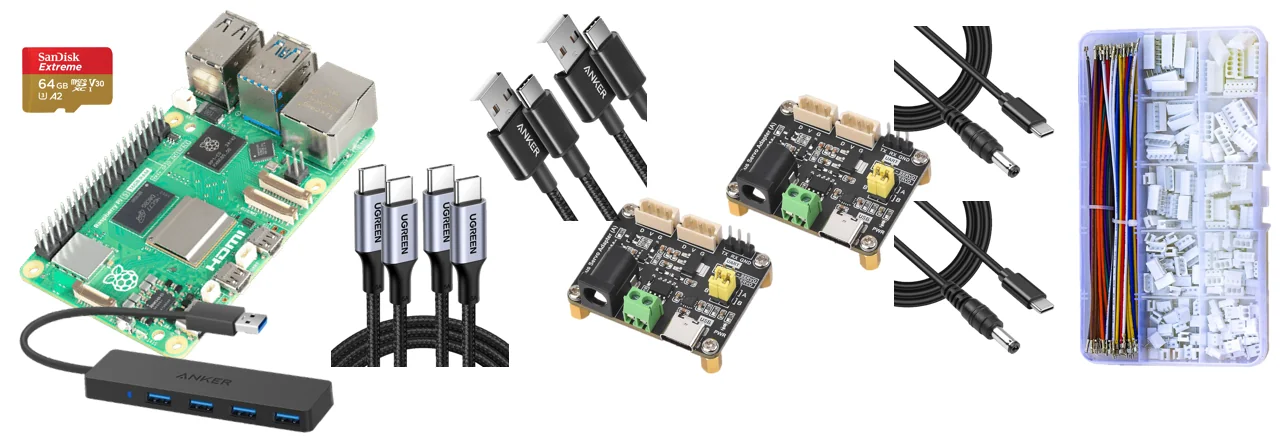
| Raspberry Pi 5 | 1 optional | A laptop can be used instead |
| Motor controller boards | 2 | For the two SO-101 arms |
| microSD card | 1 | Required when using Raspberry Pi |
| USB-C / USB-A cables | 2 | Motor-controller data connections |
| USB-C to DC 12V cables | 2 | Controller-board power |
| Long 5264 / 3-pin motor wiring | 1 set | Route across the cart and arms |
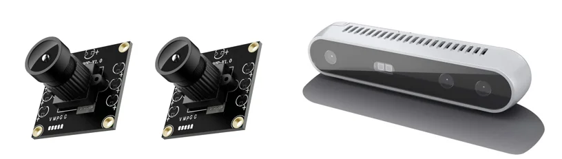
| Hand cameras | 2 | Wrist or hand views |
| Head camera | 1 | Logitech C920 or equivalent; depth camera is optional |
Required tools
M3 screw and nut set with hex driver, flush cutters, screwdrivers, and nine M4×10 screws for wheel assembly. Use the flush cutter for cable-routing mesh.
Compatibility notes
A different cart can work but may need changes to printed connectors. Alternative batteries must supply approximately 120 W for arms and wheels, plus about 40 W for a Pi if used.
3. Manufacturing
3D-print the structural components
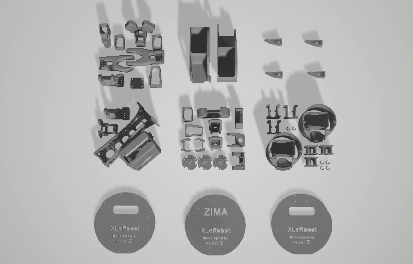
The project divides the printable set into SO-101 arms, arm-base components, neck and head pieces, and the selected wheel-base parts. Confirm the wheel-base choice before printing because those parts are configuration-specific.
Before printing
- Inspect the required part list by subsystem and print only the matching wheel-base set.
- Plan supports, orientation, and bed size before starting large arm-base or cart components.
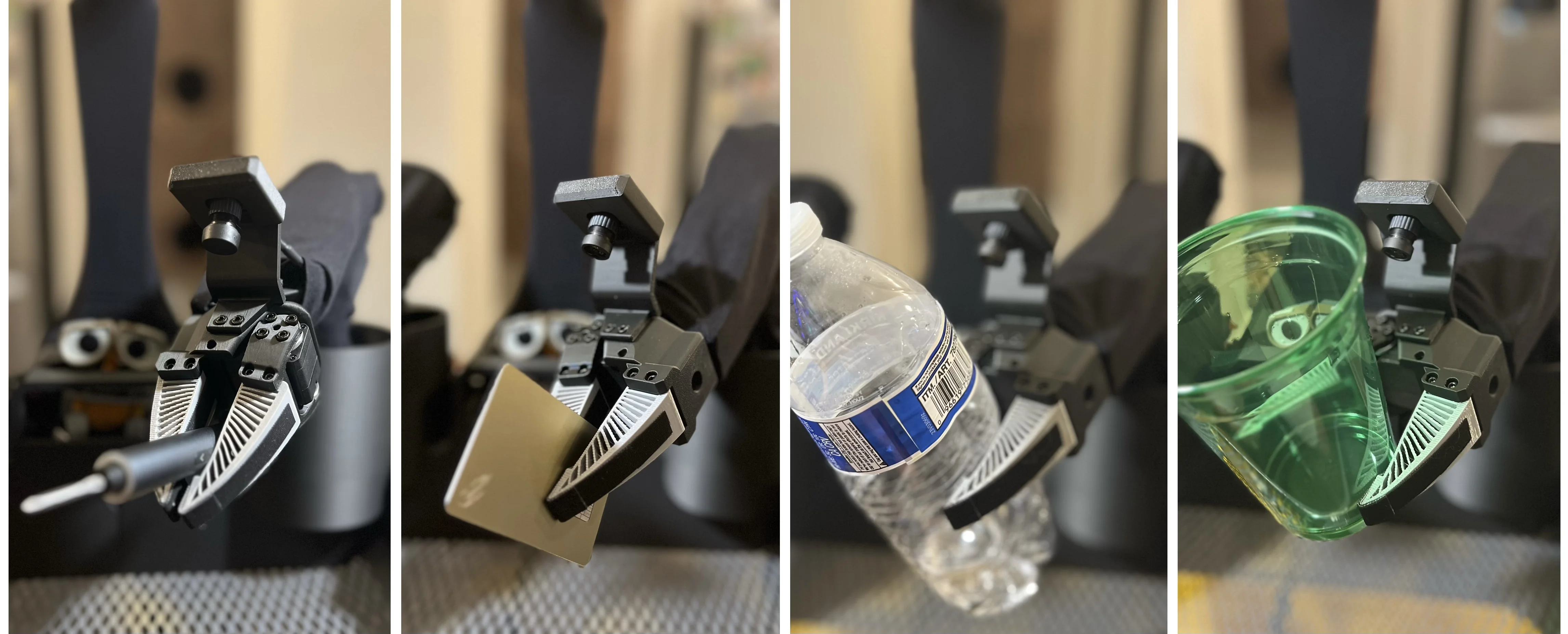
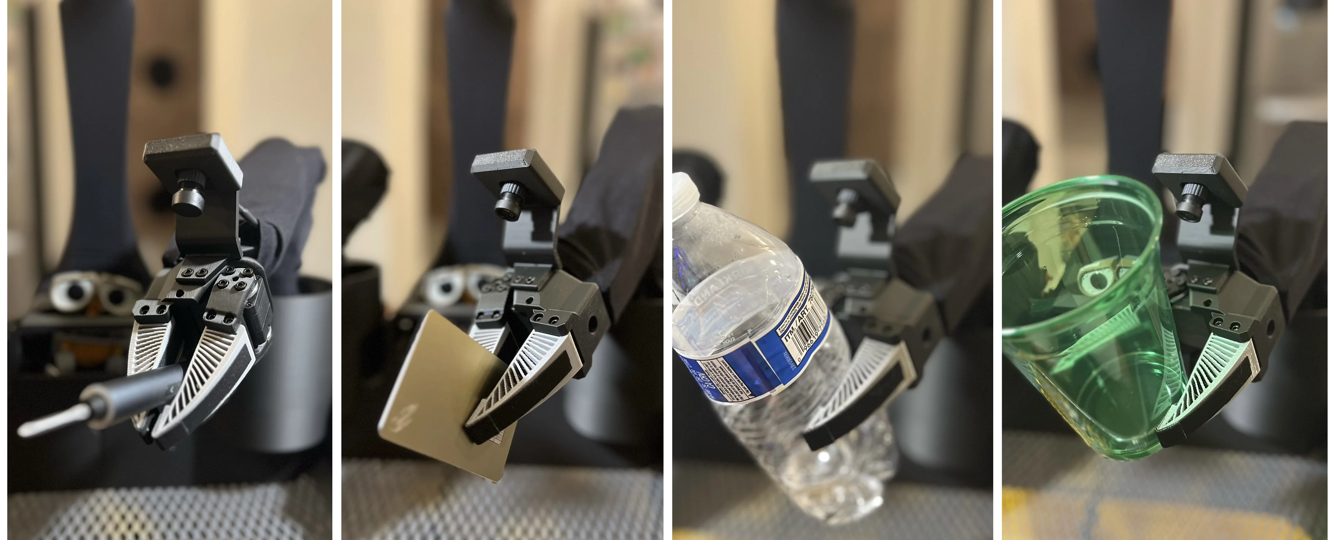
- Use the specified flexible material for soft finray gripper fingers when that option is chosen.
Optional printed additions
- Soft gripper fingers require TPU95A.
- Standard SO-101 fingers remain an alternative.
- Visual sleeves and other cosmetic pieces are optional and do not affect the core build.
4. Mobility
Choose and build the wheel base
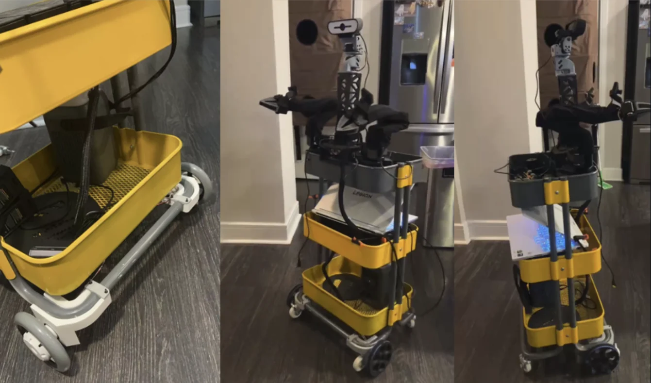
Build one complete mobile base before installing it under the cart. The current dual-wheel design is more stable, faster, and has more torque than the three-omni-wheel approach; it comes in servo-motor and brushless-motor versions. The project also documents the mecanum-wheel configuration.
Servo-motor version
This is the easier option for wiring and control because it remains in the Feetech servo ecosystem. It is more stable and accurate than the earlier platform, with less movement play. In exchange, it loses sideways motion and remains limited by servo noise, speed, and torque.
Additional non-printed parts
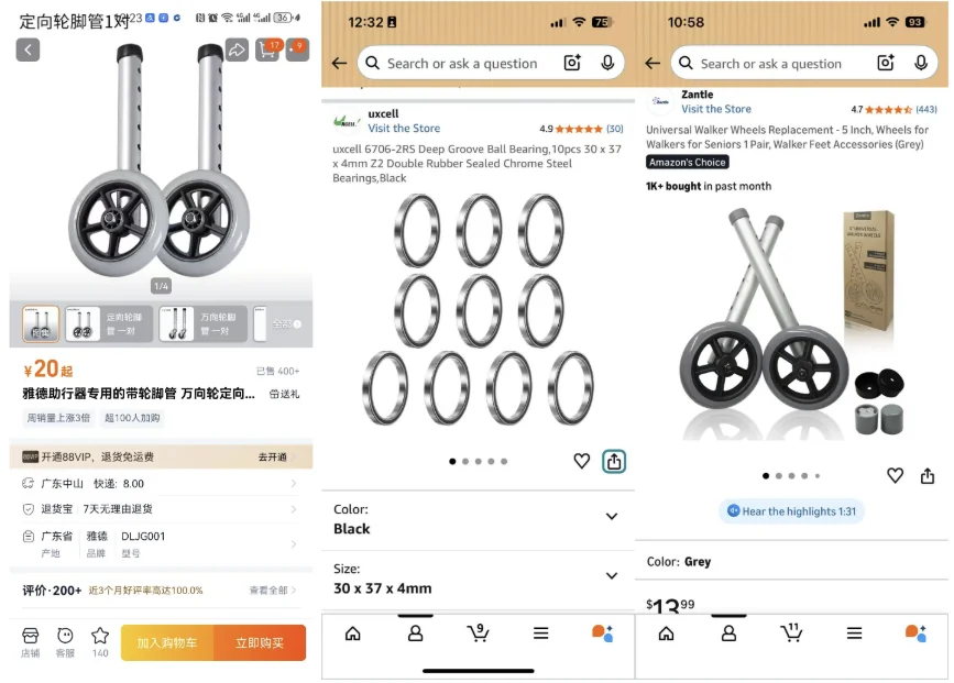
- 5-inch universal walker wheels
- 30 × 37 × 4 mm bearings
- Longer motor cables or an extension kit
Brushless-motor version
This version is based on the Bracket Bot wheel-base approach. It targets a more robust and capable platform, but adds wiring complexity. Its cart connector uses M8×20 screws.

Mecanum base
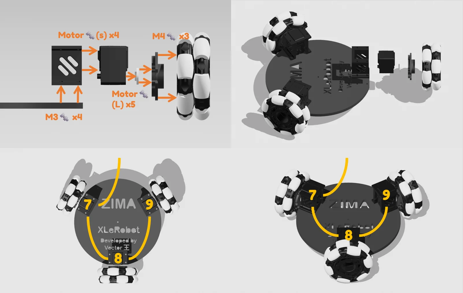
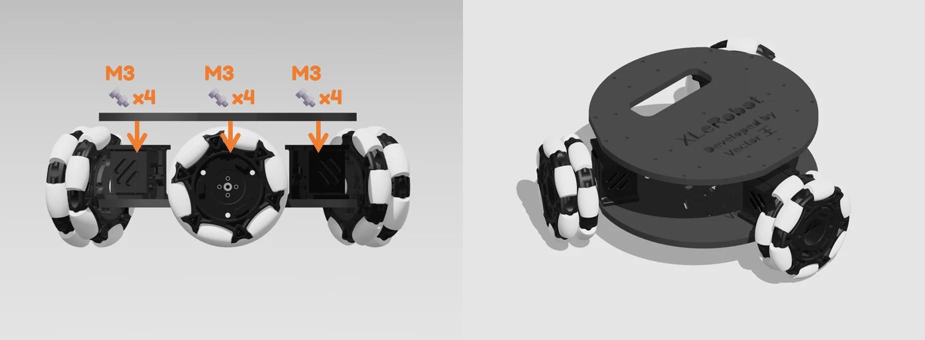
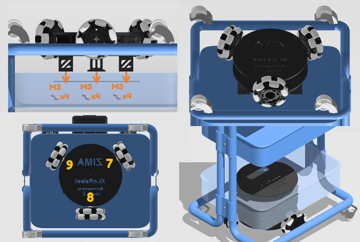
Use the three-wheel X-pattern layout, fit the motors, and confirm direction before keyboard teleoperation. The complete wheel base includes non-printed mechanical and electronic parts.

5. Manipulation
Prepare the SO-101 arms
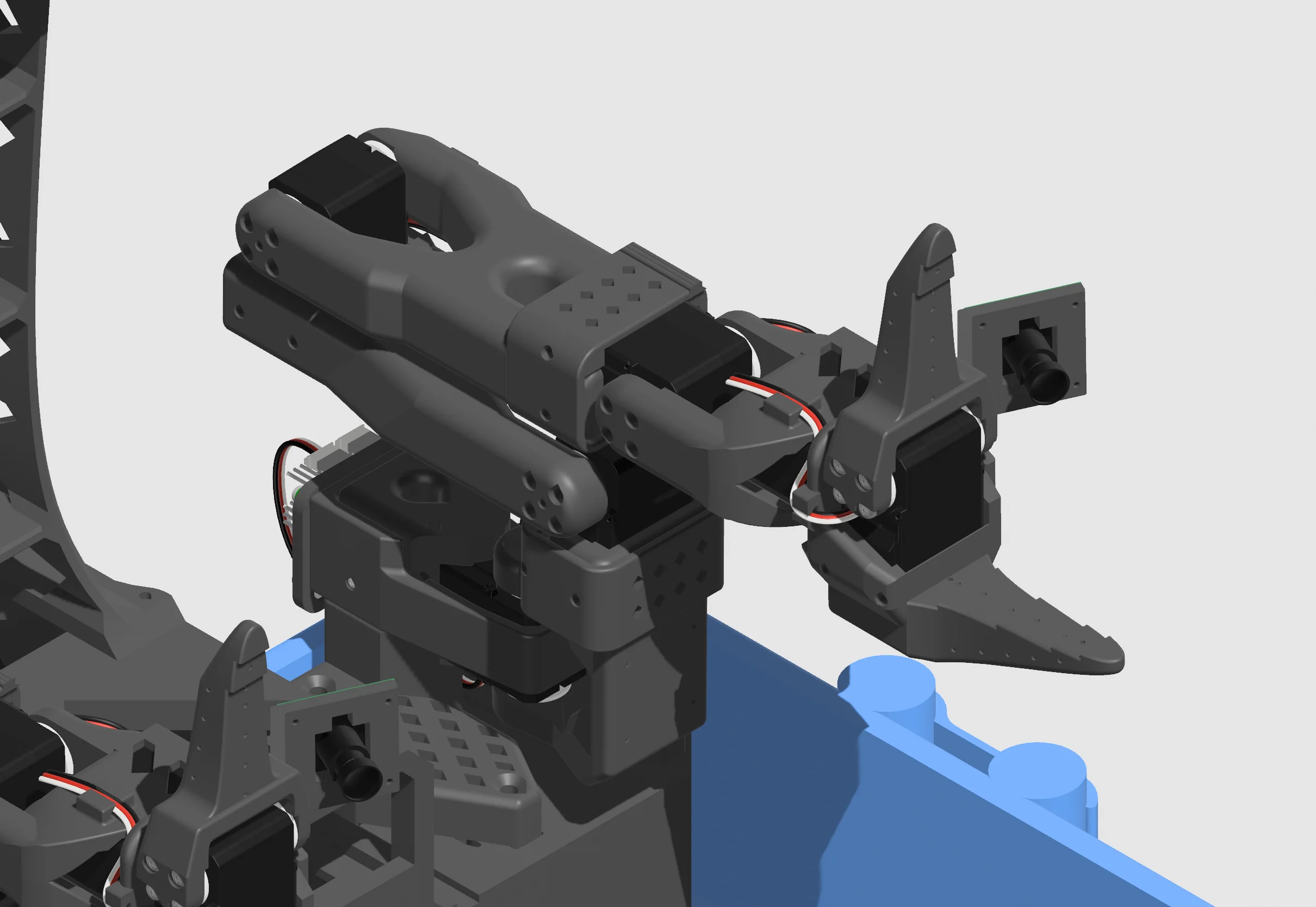
Build, configure, and calibrate both SO-101 arms before mounting them to the XLeRobot platform. The project uses twelve arm motors in total. Keep controller cables labelled and make sure both arms move correctly on their own before they are installed above the mobile base.
Open the SO-101 assembly and calibration guide →6. Integration
Assemble the platform in this order
- 1. Prepare the cart.
Build the cart chassis and prepare its cable-routing and attachment points.
- 2. Install the selected wheel base.
Secure the mobile base to the cart only after it has passed its standalone mechanical checks.

- 3. Build the arm base.
Assemble the top base and head assembly, then prepare the mounting positions for both SO-101 arms.
- 4. Mount arms, cameras, and controllers.
Install the completed arms and sensors while preserving clear cable paths and full joint travel.
Official assembly video
Additional assembly video
7. Electrical integration
Wire the system and install the battery
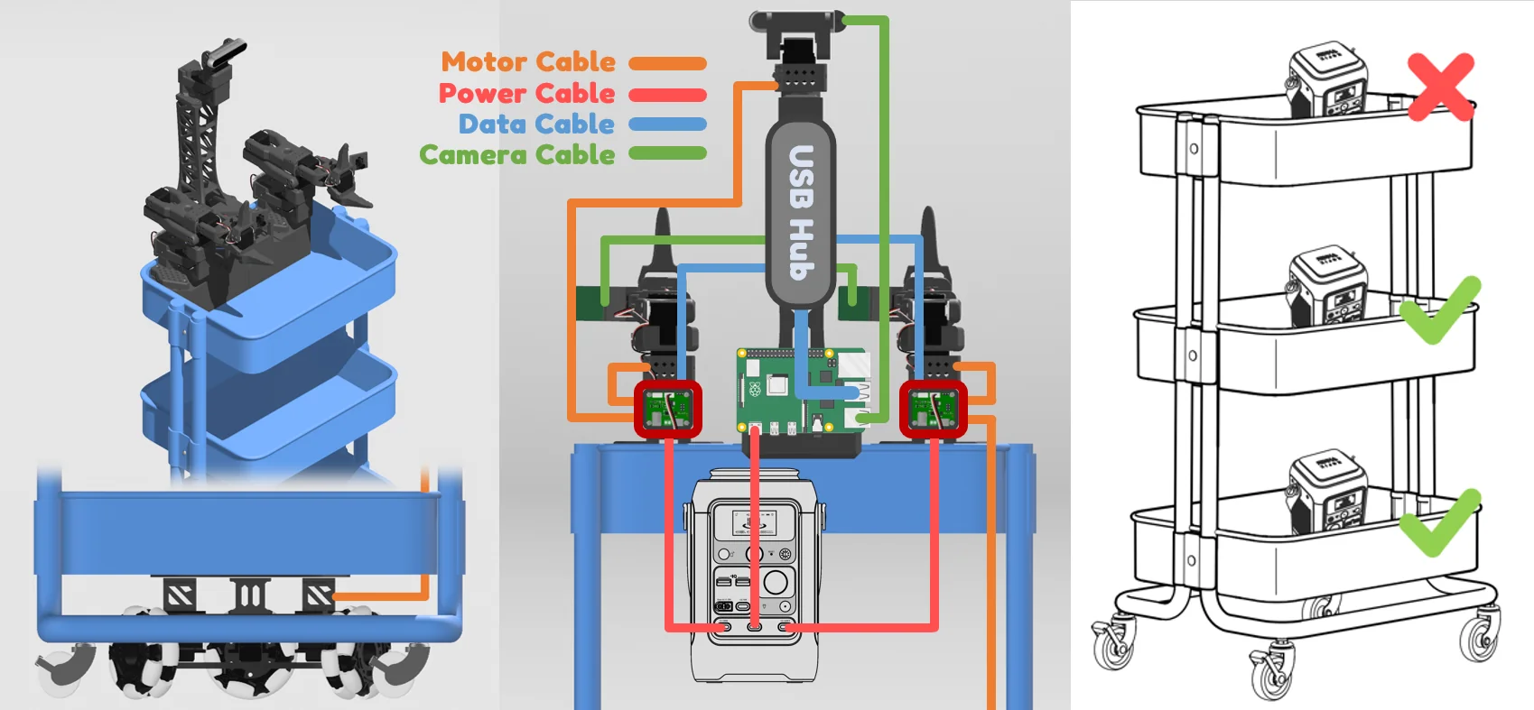
Run long motor wiring through the cart only after each mechanical path is final. Connect each arm controller, the selected base hardware, cameras, Pi or laptop interface, and power wiring according to the chosen configuration. Place the battery/power station so its cables cannot enter the wheel or arm travel paths.
8. Complete the build
Final assembly and first checks
Finish by securing the base in the cart, checking all structural fasteners, placing cameras and optional visual covers, then testing the system in stages: power, wheel direction, arm communication, arm motion, camera feeds, and higher-level control. Do not attempt full-speed driving or dual-arm movement until every individual subsystem is behaving correctly.
Detailed hardware reference
Platform specification and design choices
The documented XLeRobot 0.3 platform combines an IKEA RÅSKOG cart, a selectable mobile base, two SO-101 arms and a portable power station. A typical completed configuration is about 12 kg, approximately 0.5–1.25 m tall and around 0.36 m wide from the cart edge. The main computer performs higher-level computation; a Raspberry Pi can handle local communication over Wi-Fi.
Power target
The reference uses a 288 Wh / 300 W power station. Normal use targets more than 10 hours; 280 W input can recharge it in about one hour.
Cart choice
RÅSKOG was selected for availability, low cost, metal mesh mounting points, storage, and a practical household footprint.
Cameras and compute
The documented options include two hand cameras, a Logitech C920 head camera and an optional RealSense D415. A laptop can replace the optional Pi.
Detailed bill of materials
Configuration, alternatives and optional additions
The upstream basic configuration was estimated around USD 660 before printing, tools, delivery and taxes. Stereo dual-eye cameras add roughly USD 30, a Raspberry Pi about USD 79 and a RealSense camera about USD 220. These are historical sourcing references, not RobotEd prices.
Core hardware
- 17 STS3215 12V servos: 12 arms, 3 base, 2 head.
- Two arm controllers, long 5264 / 3-pin cable set, controller data cables and two USB-C-to-12V DC cables.
- Three 4-inch omni wheels for the reference three-wheel base, or selected dual/mecanum hardware.
- M3 screws/nuts, flush cutter, screwdriver and nine M4 × 10 screws.
Alternatives and upgrades
- STS3250 servos provide more torque at materially higher cost.
- Alternative power stations need two 60 W+ USB-C feeds plus Pi power when used.
- Optional parts include TPU95A finray grippers, extra SO-101 leader sets, sleeves and Quest 3/3S workflow hardware.
- Different carts or batteries can need mechanical or electrical changes.
Detailed print preparation
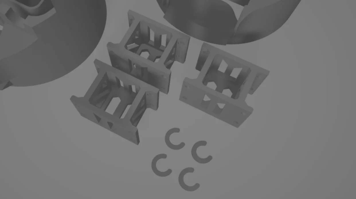
Plan printable parts by subsystem
The source build was demonstrated in matte black PLA on a Bambu A1. PETG HF, PLA-CF and tough PLA are listed alternatives. Use normal slicer practice for orientation, supports, infill and speed; in humid conditions, dry PLA at around 45 °C for eight hours. A 3MF stores models, not a universal ready-to-print support plan.
Arms and platform
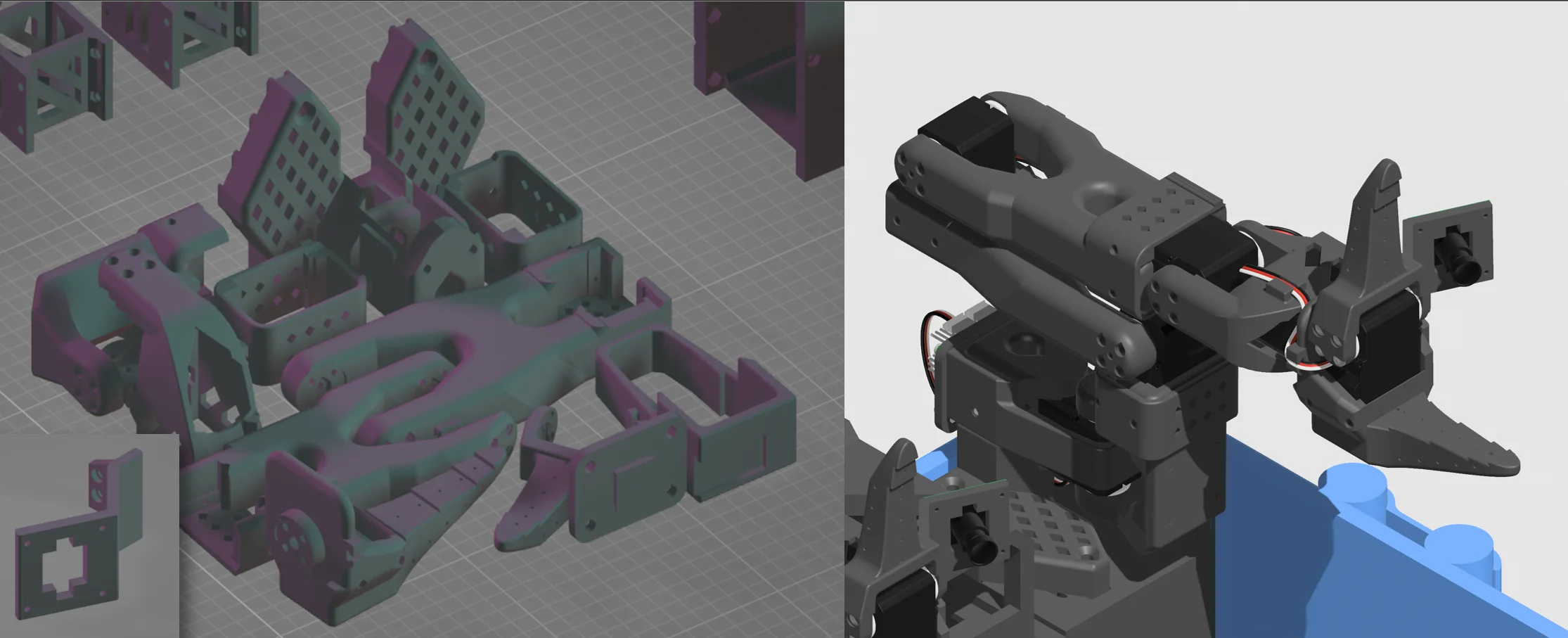
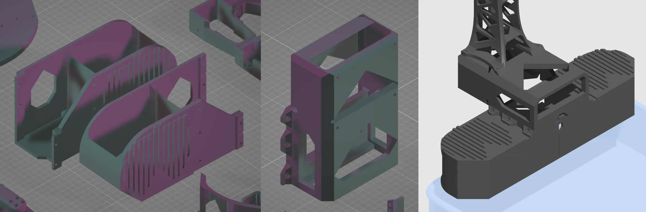
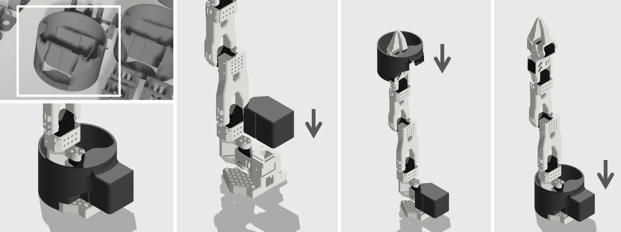
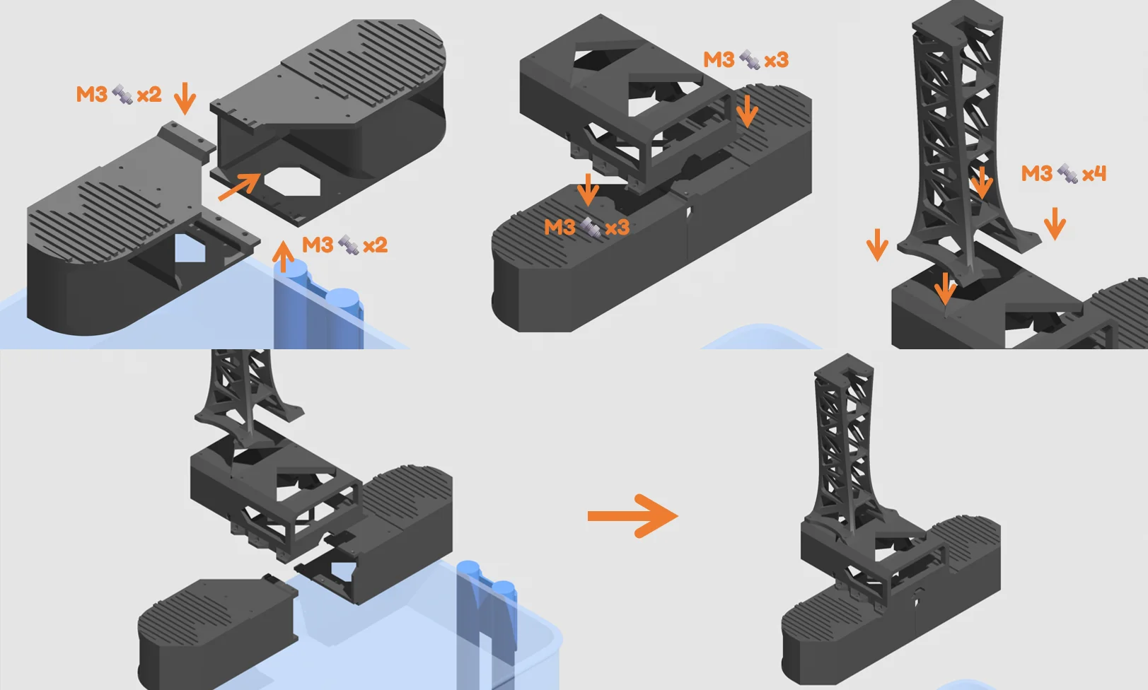
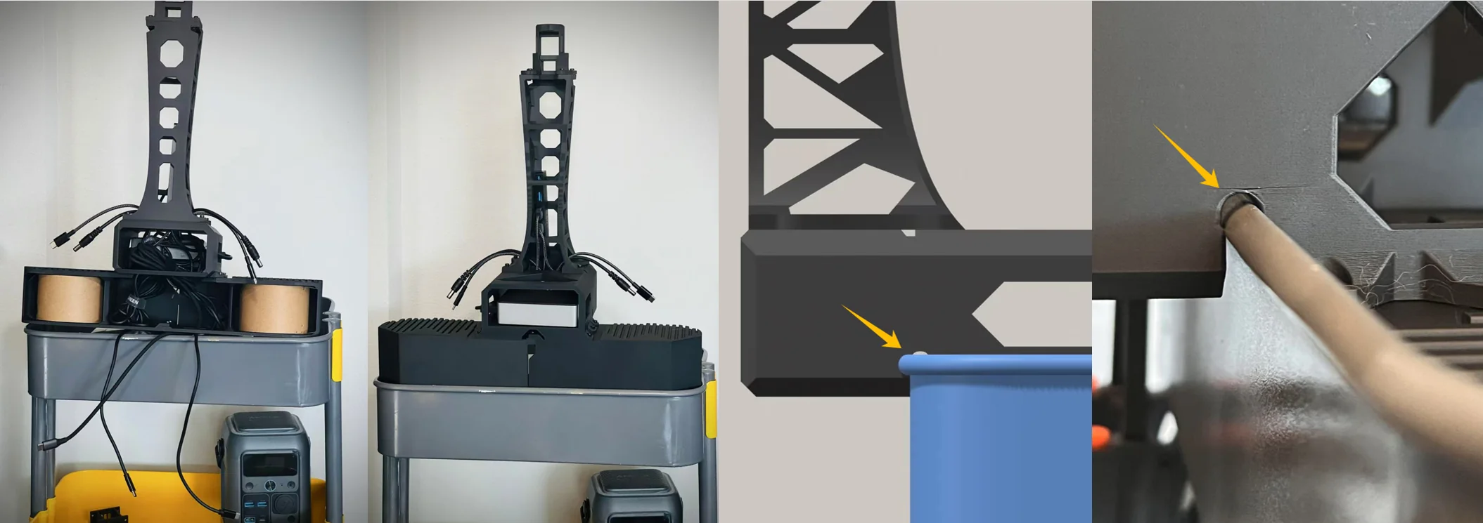
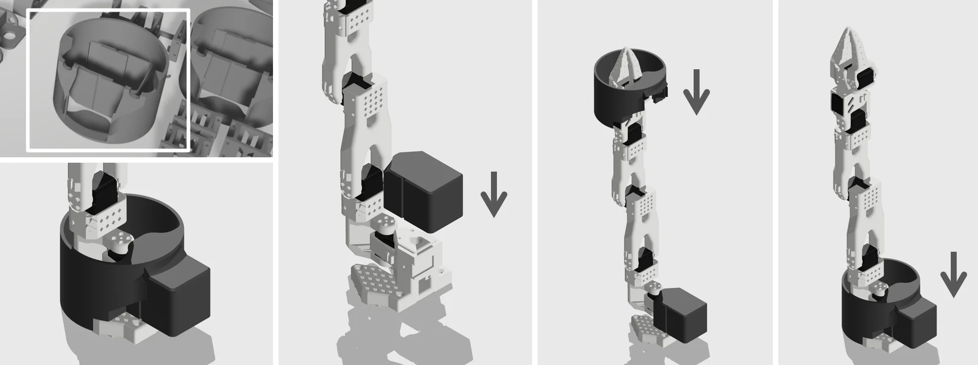
Print two follower SO-101 arms. Leader arms are only required for simultaneous leader-follower joint control. The platform uses two arm bases, a central storage shell and a reused Bambu cardboard filament spool as structural support.
Head and wheel parts
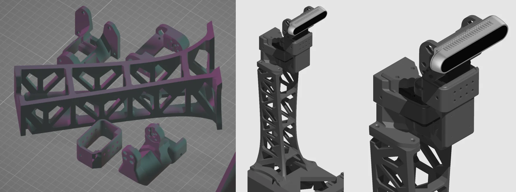
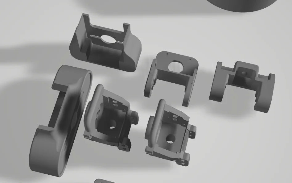
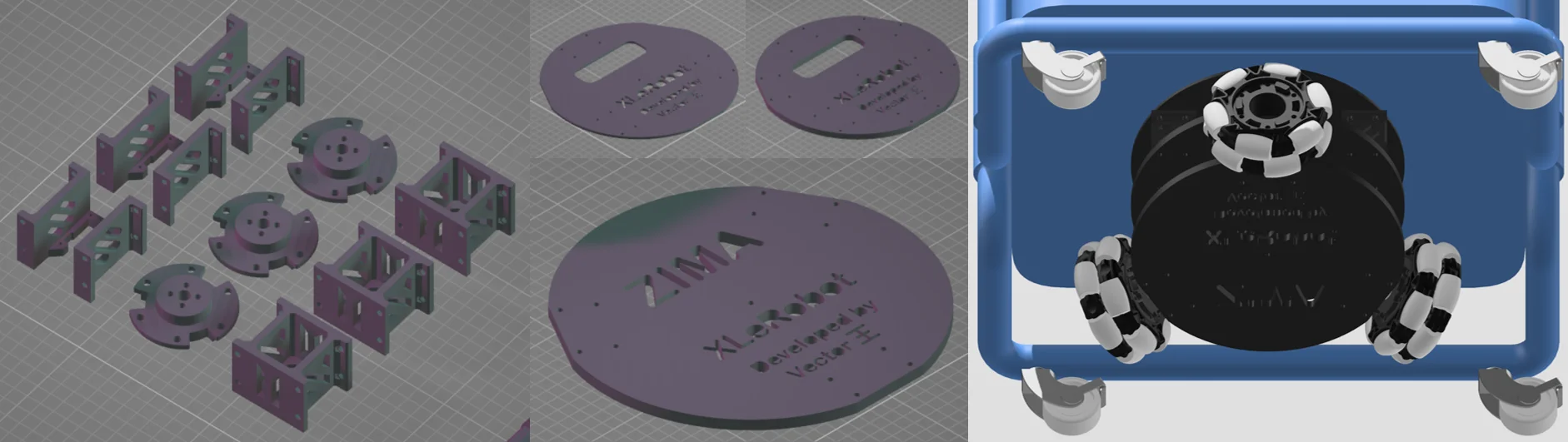
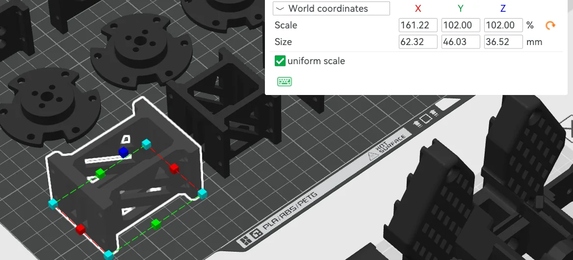
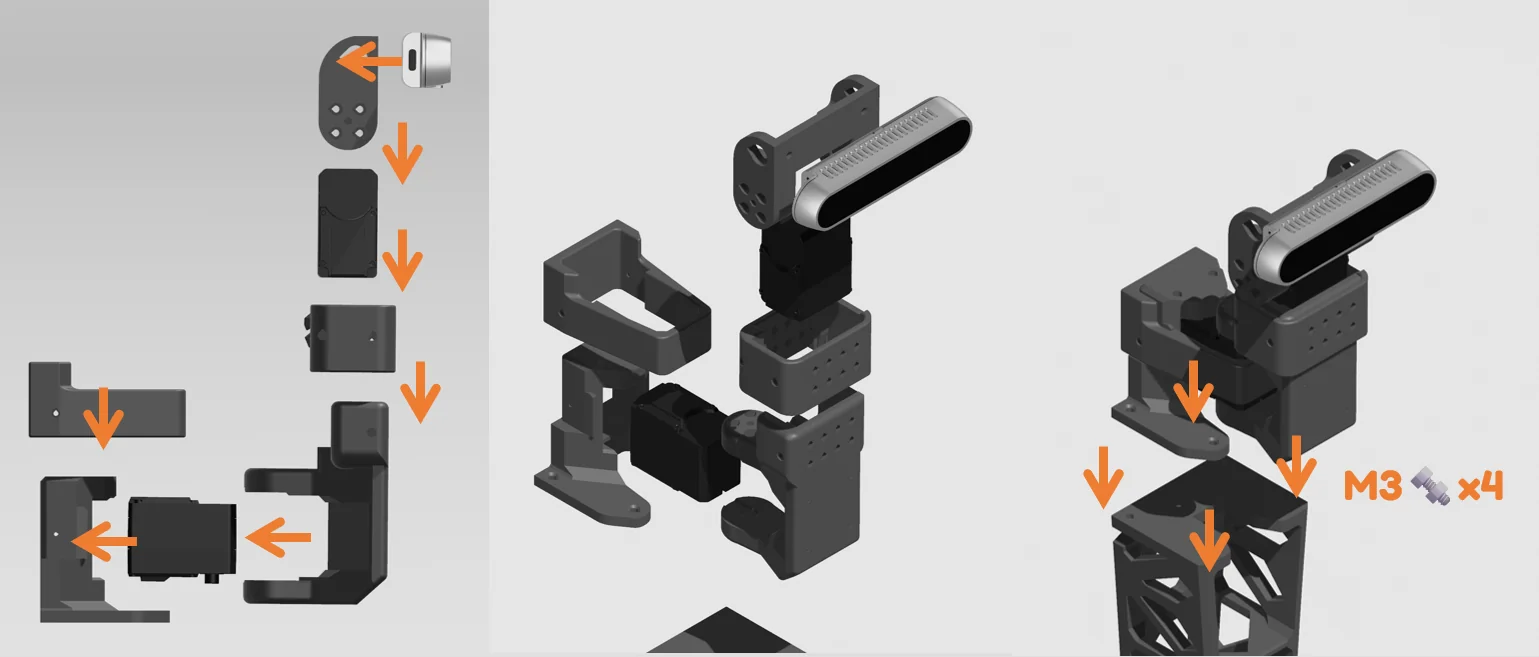
The neck/head derives from the first two SO-101 links, with shells for webcam, RealSense or hand cameras. For the three-omni base, adjust only cart-connector Z scale to balance wheel pressure; washers are an alternative.
Detailed mobile-base options
Dual-wheel and mecanum instructions
Dual-wheel servo base
This simpler option trades lateral movement for accurate positioning and reduced play. Use 5-inch walker wheels, 30 × 37 × 4 mm bearings and extended motor cables. Keep it elevated for the first direction test.
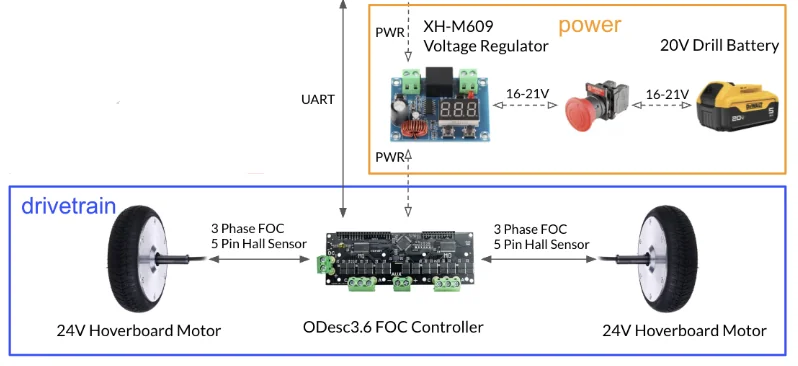
Dual-wheel brushless base
Based on the Bracket Bot approach, this targets a more capable chassis but brings more complex wiring. Its cart connector uses M8 × 20 screws.

software/examples/4_xlerobot_teleop_keyboard.py: i/k forward/back, j/l sideways and u/o rotation. The reference second-bus IDs are 7–10: front-left, front-right, rear-left, rear-right; adjust software if your wiring differs.Detailed platform assembly
Complete the integration carefully
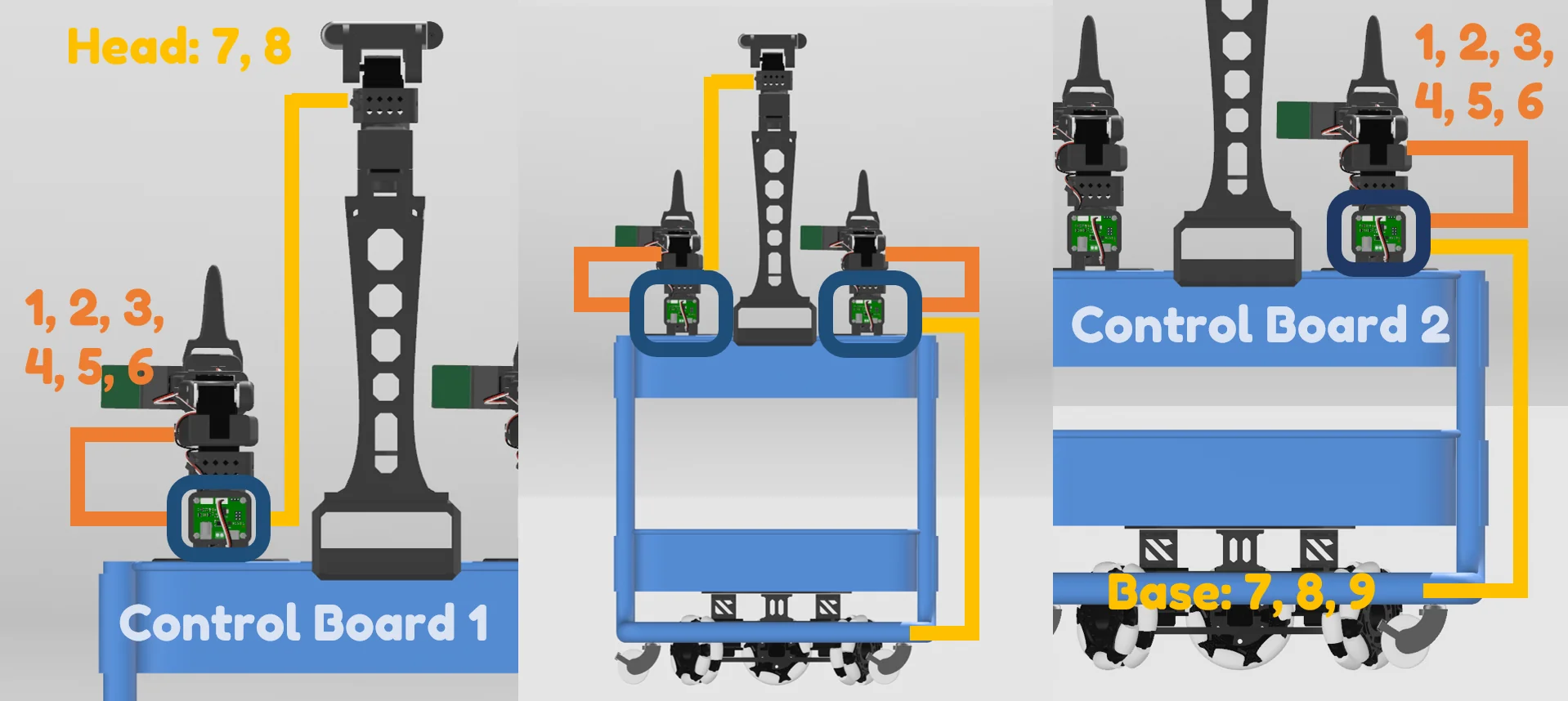
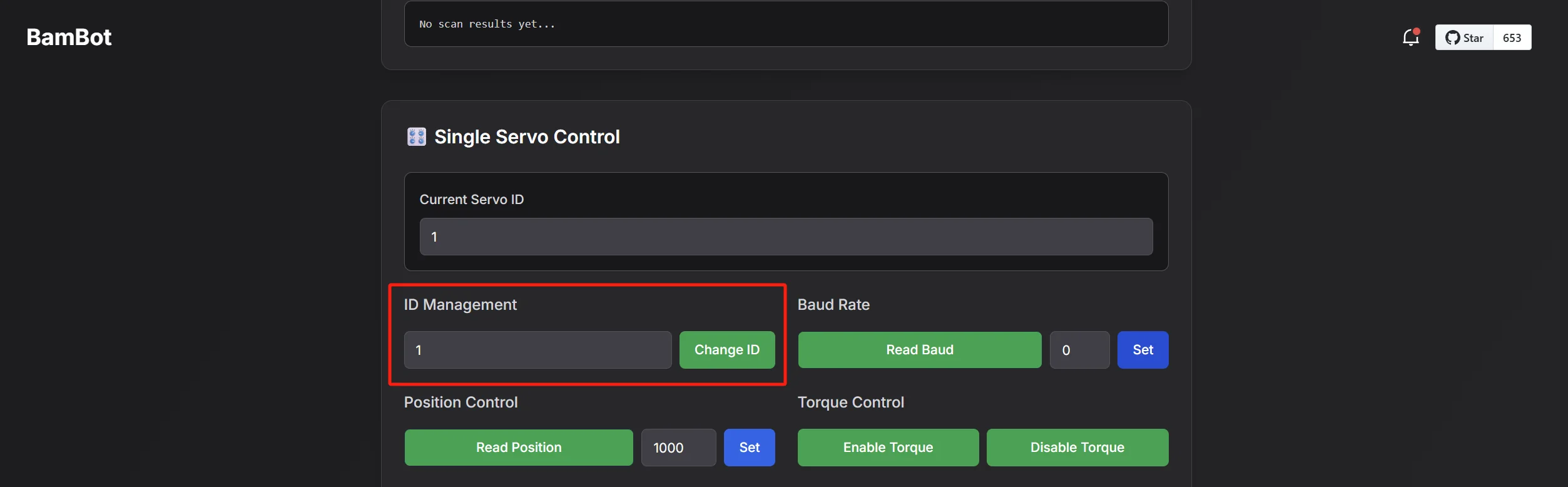
- 1. Configure and label motors. Allow two to four hours from loose parts, or one to two once both arms are ready. Configure each motor individually, grant serial access on Linux, and label left/right arm IDs 1–6, head IDs 7–8 and wheel motors.
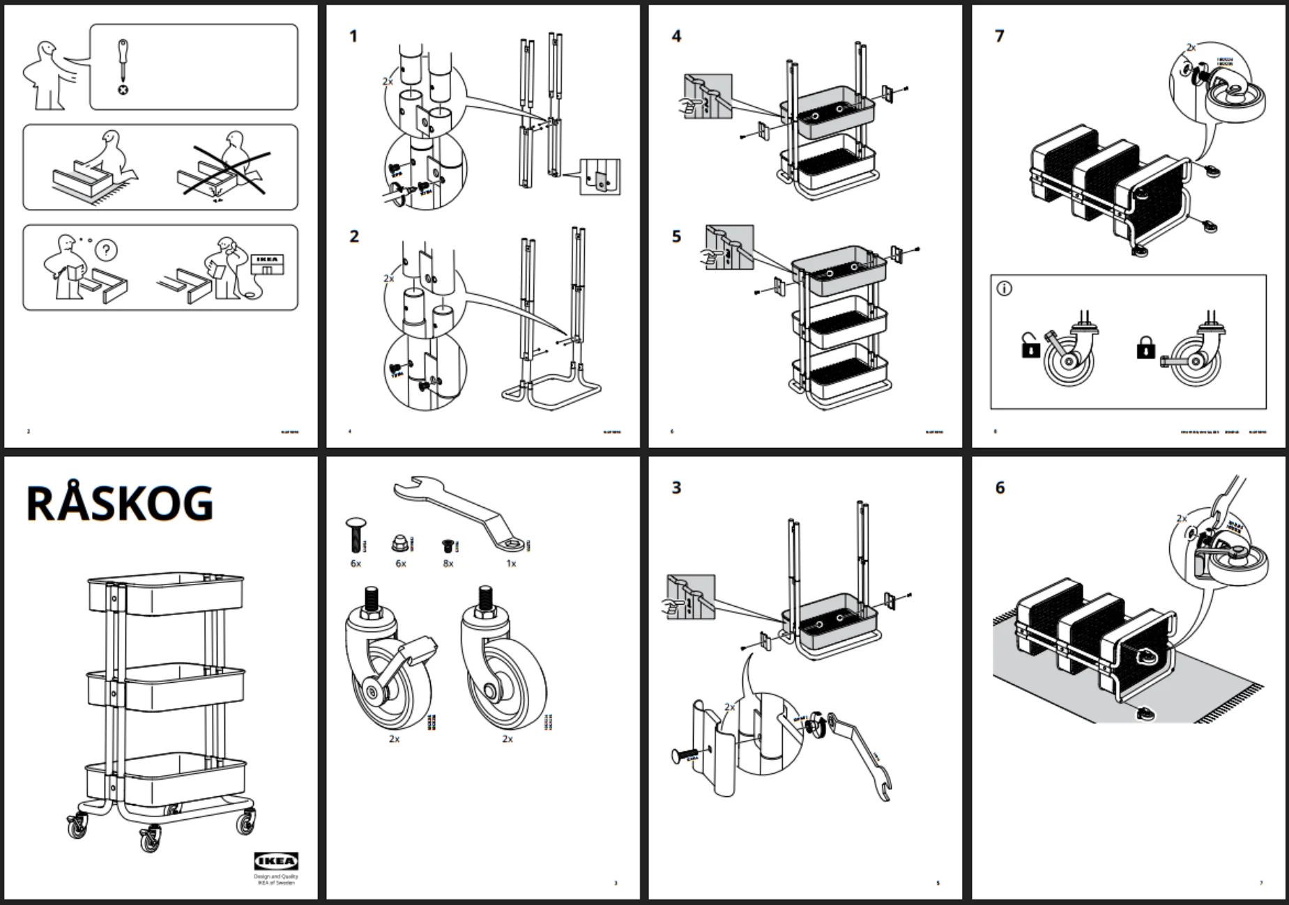
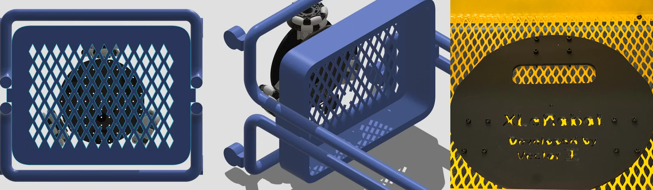
- 2. Prepare cart and wheel base. Remove temporary LeKiwi battery mounts, stack plates in the documented order, use extended motor wiring, and adjust connector height until wheel pressure is even. Cut only the central X section of mesh for cable routing.
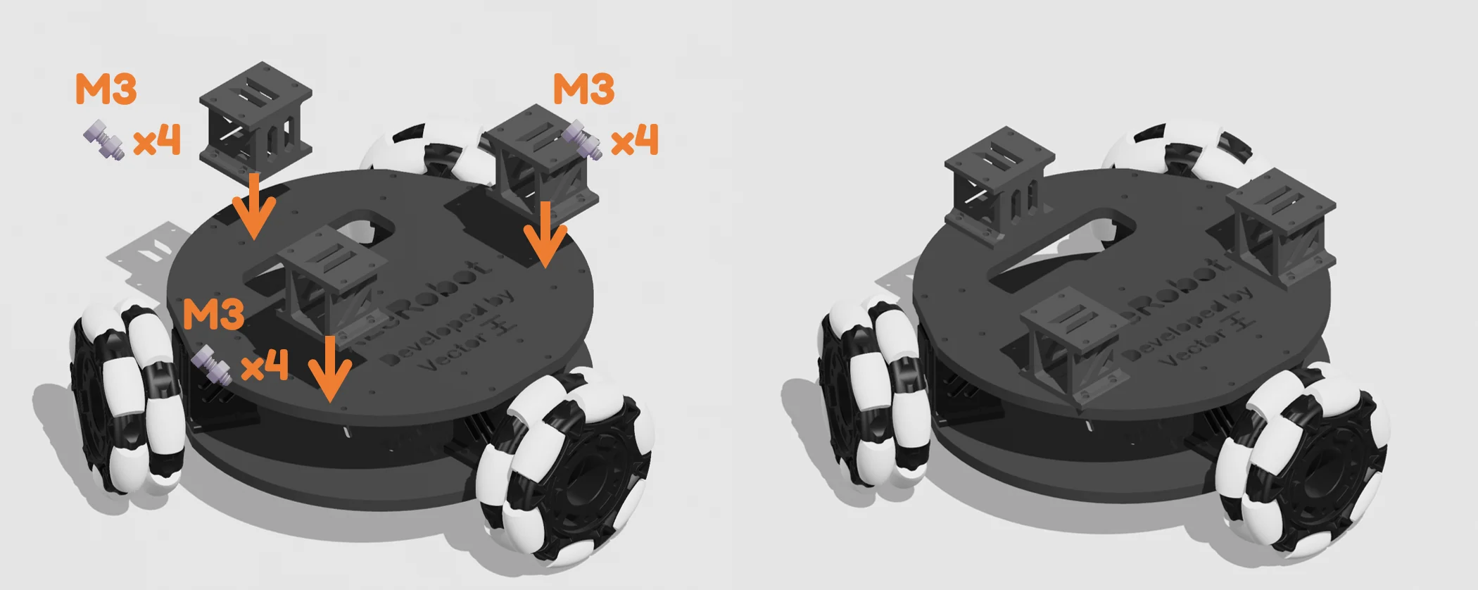
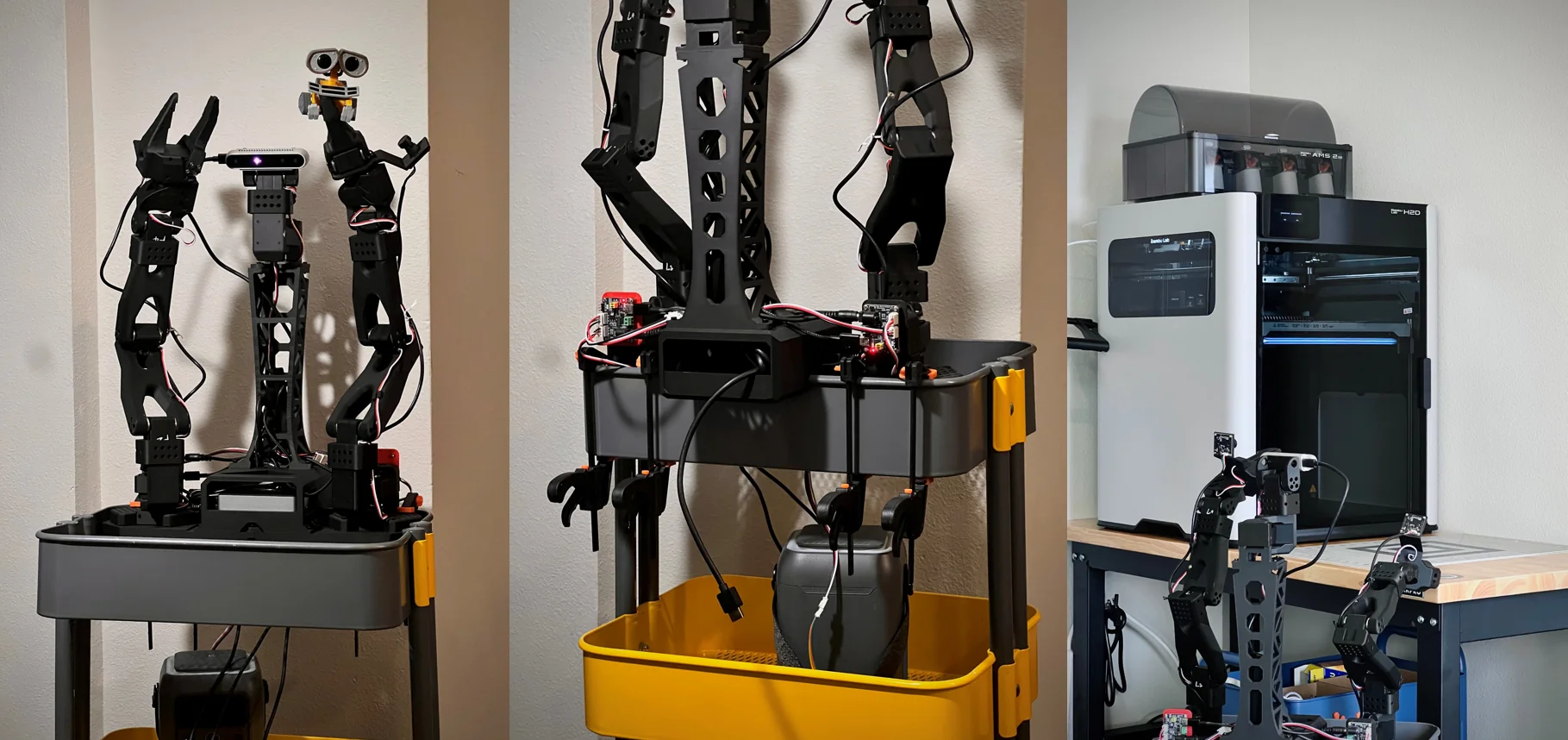
- 3. Fit platform, arms and head. Assemble the arm base upside down, fit the head as the first two SO-101 link stages, then secure arm bases at the top corners. Check every arm clears cart, cables and cameras.
- 4. Wire before final clamps. Route controller data to the Pi, reserve Pi USB ports for cameras, observe 12V polarity on 5264 leads and use separate power feeds for the two controllers and Pi.
- 5. Power and inspect. Place the power station on the middle or lower shelf, connect power last and disconnect it before changing plugs. Lift the approximately 12 kg robot rather than pushing it, and retighten wheel connectors after driving.
Attribution
XLeRobot open-source hardware documentation
This tutorial reproduces and organizes material from the XLeRobot documentation for the XLeRobot 0.3.0 hardware project. Copyright © 2025 XLeRobot Contributors. Licensed under the Apache License, Version 2.0. RobotEd is independent of the project authors.